Page 1 of 1
belt sander question
Posted: Thu Jun 27, 2019 2:39 pm
by sfwood
Hi all,
Had my belt sander apart yesterday to install the dust port upgrade. In putting it back together I saw that the wide silver disk with the four holes in its edges that holds the sander body on the trunion just spins the lock nut unless you reach inside and hold the nut or put a socket on it. It occurred to me that maybe the disk isn't meant as the lock mechanism and I am missing some parts. The parts diagram at SS seems to show a bolt in the other hole that is over the trunion but the pictured bolt doesn't seem to have a quick tightening knob or any such, and the bolt doesn't appear in the photo in the belt sander instructions at SS (see photo). The instructions are mum on locking the sander body in place. Do I just tighten the disc w/ the four holes enough that I can still move the sander and call it good? Would appreciate any enlightenment.
Thanks, Steve
Re: belt sander question
Posted: Thu Jun 27, 2019 3:08 pm
by dusty
I can not say with certainty that what I have is standard configuration or not but I have a bolt and nut there that secures the belt sander where I want it. Without the bolt and nut, I can not secure the sander position.
Re: belt sander question
Posted: Thu Jun 27, 2019 10:05 pm
by JPG
The silver thingie with the holes is secured by a nylock nut and cup on the other side. It's purpose is to provide friction so as to preclude a deadfall. The bolt holes(There is another that is out of view in your picture) provide a means to tightly clamp the hinge at the extreme positions and possibly at positions between. That other hole would be the one to use in the tilt position shown in your picture. The holes should be used with a bolt, a nut, and a washer both under the bolt head and a second under the nut.
Re: belt sander question
Posted: Fri Jun 28, 2019 1:14 pm
by chapmanruss
Are we are talking about the same parts 20, 21, 22, 34, 35 & 36 shown below?
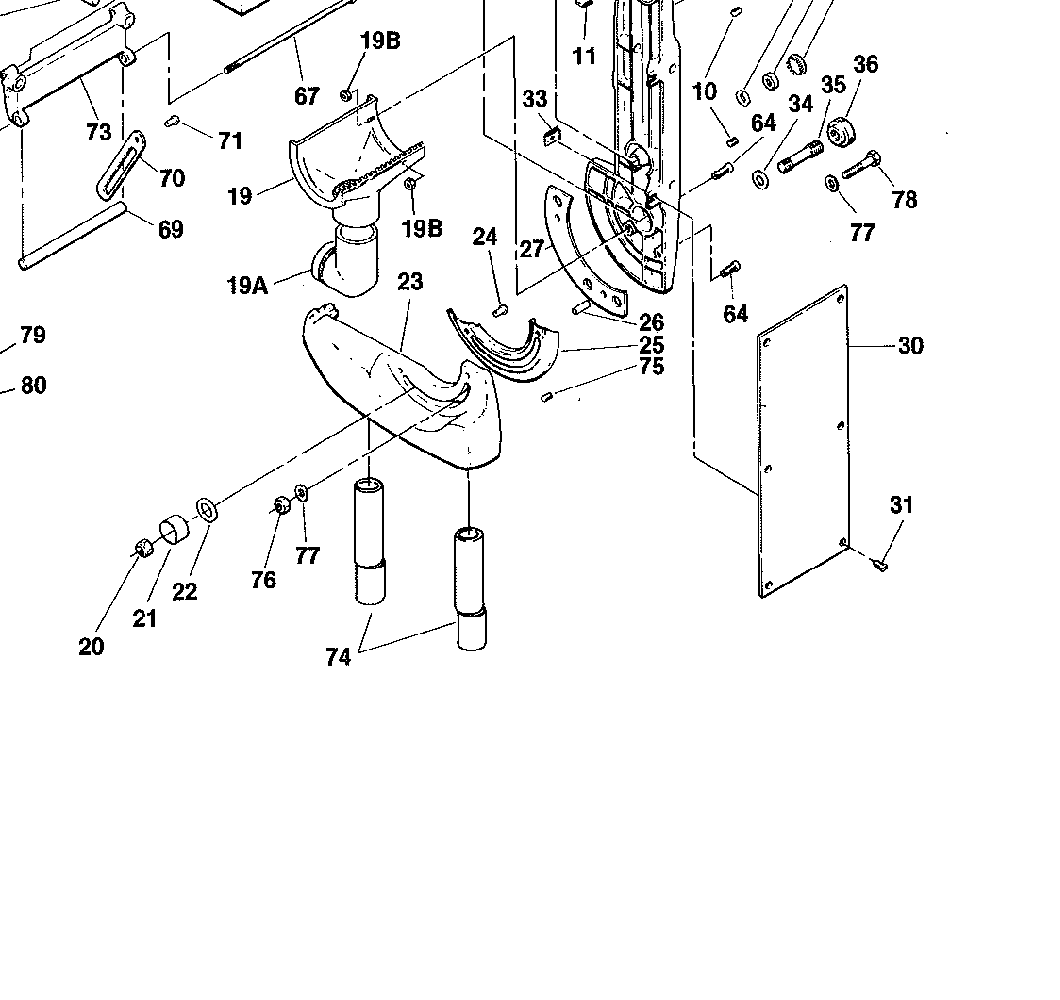
- Belt Sander - parts.png (49.11 KiB) Viewed 20106 times
If so turning part 36 either locks or unlocks the belt sander to lock in or move from/to vertical or horizontal. It should not take much of a turn to unlock it for adjustment to/from horizontal/vertical. Make sure all the parts are there. The Trunnion Lock (#36) should turn freely on the Trunnion Stud (#35). If it doesn't check and clean up the threads on both parts. You should be able to turn the Trunnion Lock to tighten and loosen it without having to hold the rear Trunnion Nut (#20). A little lubrication on those threads may help too.
The parts are
20 Trunnion Nut
21 Cup
22 Washer
34 Trunnion Washer
35 Trunnion Stud
36 Trunnion Lock
...
Re: belt sander question
Posted: Fri Jun 28, 2019 8:02 pm
by JPG
'We' also be talking about 76,77,77,78.
Re: belt sander question
Posted: Fri Jun 28, 2019 11:05 pm
by sfwood
Thanks all,
Yes to 20, 21, 22, 34, 35 & 36. 36--trunion lock / "silver disk with four holes in edge" (mine is silver, anyway) seems locked on 35, causing entire shaft/bolt assembly to spin when turned, will see about loosening that up. Yes, also asking about 76-77-77-78 which are missing on my sander. Thought perhaps 36 was not meant to be tightened fully and only 76-77-77-78 was meant as the lock (though that assembly requires tools as well).
-Steve
Re: belt sander question
Posted: Sat Jun 29, 2019 12:13 am
by reible
Maybe this will help:

- belt sander.jpg (182.52 KiB) Viewed 20033 times
Ed
Re: belt sander question
Posted: Sat Jun 29, 2019 12:59 am
by sfwood
Yes, exactly the info I was missing. That doesn't appear in the instructions I found on-line. Is that an on-line resource you pasted? Thanks.
[edit] nevermind--found it:
https://www.shopsmith.com/ss_forum/down ... p?id=26502
.
Re: belt sander question
Posted: Sat Jun 29, 2019 12:11 pm
by chapmanruss
Sorry I did not mention the Aux. Lock Bolt, parts 76 to 78. I have never used it and do not even have the bolt. My Belt Sander (from December 1977) was given to me by my father-in-law. The only other Belt Sander (from June 1989) I have had is one I restored and resold and it didn't come with the optional bolt either. Kind of out of sight out of mind. I may pick up the parts and try them out using a wing nut as suggested in the manual. The bolt is, as listed in the manual, a Hex Head Cap Screw, 3/8"-16 x 2".
Thanks, JPG and Ed for pointing that option out. I am sure others will find the information helpful.
...