A drop-leaf coffee table, end table and corner table in the classic Queen Anne style
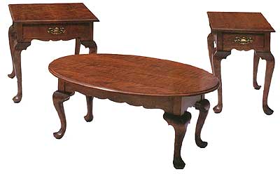
Here are three gorgeous tables that are surely destined to become the furnishing “stars” of your living room – or any room in your home. The end table and corner table feature a unique style of drawer joinery that we call a “beaver tail”. And although these tables are, by no means, a “weekend project” or one for the inexperienced, if you take your time and follow our instructions, you should be able to produce results that you and your future generations will be proud of. For the best results, we recommend that you build them one at a time instead of tackling all three at once.
We wrote the construction procedures for this project with the emphasis on the more complicated techniques…assuming that the builder has learned the other, simpler techniques from work on previous projects.
LIST OF MATERIALS
(finished dimensions in inches)
Drop-Leaf Coffee Table
| #of Pcs | Size | Descriptions | Material |
| 4** | 2-3/4 x 2-3/4 x 15-1/4 | Leg | Cherry |
| 8 | 2 x 2 x 2 | Transition Block | Cherry |
| 2 | 3/4 x 4-1/2 x 28-1/2 | Side Skirt | Cherry |
| 2 | 3/4 x 4-1/2 x 12 | End Skirt | Cherry |
| 1 | 3/4 x 16-1/4 x 40-1/4 | Center Top | Cherry |
| 2 | 3/4 x 7-1/4 x 40-1/4 | Drop Leaf | Cherry |
| 4 | 5/64 x 5/8 x 1-1/2 | Top Retainer Woodscrew | Steel |
| 2 | #10 x 1-1/4 | Roundheadd Woodscrew | Steel |
| 4 | 1-1/2 x 3 | Drop Leaf Hinge with Screws | Brass |
Queen Anne End & Corner Tables with Drawers
| #of Pcs | Size | Descriptions | Material |
| 4** | 2-3/4 x 2-3/4 x 21-1/4 | Leg | Cherry |
| 8 | 2 x 2 x 2 | Transition Block | Cherry |
| 2 | 3/4 x 5-1/4 x 20 | Side Skirt | Cherry |
| 1* | 3/4 x 5-1/4 x 12 (20) | End Skirt | Cherry |
| 1* | 3/4 x 1-1/4 x 12 (20) | Lower Front Skirt | Cherry |
| 1* | 7/8 x 1-3/4 x 12 (20) | Upper Front Rail | Cherry |
| 1* | 3/4 x 16 (24) x 24 | Top | Cherry |
| 1* | 7/8 x 4 x 10-5/8 (18-5/8) | Drawer Front | Cherry |
| 2 | 1/2 x 3-3/16 x 20-1/2 | Drawer Side | Utility Wood |
| 1* | 1/2 x 2-11/16 x 9-1/2 (17-1/2) | Drawer Back | Utility Wood |
| 1* | 1/4 x 9-1/2 (17-1/2) x 19-3/4 | Drawer Bottom | Plywood |
| 2 | 3/4 x 1-1/2 x 19-3/4 | Drawer Glide | Hard Maple |
| 6 | 1/4 Dia. x 1 Long | Drawer Dowel | Birch |
| 1 | 1-3/4 x 3-3/4 | Drawer Pull | Brass |
| 4 | 5/64 x 5/8 x 1-1/4 | Top Retainer Woodscrew | Steel |
| 4 | #10 x 1-1/4 | Roundhead Woodscrew | Steel |
* Increase the length of these pieces as shown in parentheses to make the End Table into the Corner Table and double the number of pieces required.
** Add 1/4″ to the length if making a higher foot pad for use on plush carpeting.
Buying your materials
Regardless of whether you decide to build all three tables at once or one at a time over an extended period, it is extremely important that you purchase all of your materials at the same time to avoid miss-matches.
You’ll need both 1″ and 3″ thick cabinet hardwood…preferably cherry, maple mahogany or walnut for this style of furniture. Buy 32-3/4 board feet of 3″ (12/4) and 27-1/2 board feet of 1″ (4/4) stock.
You’ll also need a 1/2″ x 7″ x 60″ piece of utility wood (poplar or similar) for the drawer sides and backs and a 3/4″ x 7″ x 20″ piece of hard maple for the drawer glides. Add to this a quarter-sheet of 1/4″ plywood and a 14″ long piece of ¼” birch dowel, plus the required hinges, drawer pulls, top retainers and wood screws. See the List of Materials for a complete, detailed shopping list.
Starting construction
Before you get started, be sure to check the alignment of all your machinery. With this project, precision cuts are CRITICAL! For that reason, it’s also a good idea to re-check machine alignment periodically as you progress through the various stages of the project.
Start by cutting your stock to size according to the List of Materials. Do not cut the tabletop stock until later to minimize the potential of damage. Also, don’t cut the drawer parts yet so they can be cut to exact size once the tables have been assembled.
If you’re planning to place these tables in a room with thick, plush pile carpeting, you might want to consider making the foot pads of the legs 1/4″ longer. This will allow the pads to sink deeper into the carpet without hiding the lower portion of the foot.
Cutting the patterns
While the glue is drying on any pieces of stock that have to be glued to size, lay out the Leg, Transition Block, Skirt and Lower Rail patterns on some plywood template stock. The Leg templates are made in two pieces. This is because the pattern must be drawn on the inside of the Leg on two surfaces.
Use a Scroll Saw or Bandsaw to first cut your template contours, then use your 2-1/4″ diameter Shopsmith Drum Sander or your Extra Long Drum Sanding Set, a file and some sandpaper to smooth your templates. Be sure to keep the profiles and corners sharp when sanding.
Once your glued-up pieces are dry, cut them to final size.
Lay out and cut the leg joinery
Always position the sapwood on the inner corner of your Legs and mark the two outside faces. Accurately mark the reference lines around all four sides of each Leg. This line will be very important later on for positioning the Transition Blocks and the templates. Also, lay out an example of each mortise and socket on the top ends and sides of each different Leg. These are your pattern Legs.

Using the Horizontal Boring mode of your MARK V with a 1-1/4″ diameter Forstner or Multi-Spur Bit, drill the round sockets in the top ends of all the front End Table and Corner Table Legs.
Switch to the Drill Press and use your Rip Fence with a shop-made fence extension, Flip-Up Rip Fence Stops and a 7/16″ Brad Point Drill Bit to cut the mortises in each Leg.
Before gluing the Transition Blocks onto the Legs, take extreme care to match the grain pattern (edge grain and face grain). Align the top of the Transition Block EXACTLY with the reference line and mark each Block position of each Leg. Some exchanges may be required for the optimal matches.
Compound cutting the Legs
Start by tracing the leg patterns onto the insides of each leg. Use a Bandsaw Fence with a stop block to accurately (and consistently) cut the top post of each leg. This will save you a lot of time when the posts are later smoothed.

Using your Bandsaw with a 3/16″ Blade, compound cut the Leg profile onto each Leg. Cut out all four Legs following the pattern shown in the plan. Remember to always cut to the OUTSIDE of the pattern line, so you can later use a Drum Sander and file to bring the Legs to their final dimensions.
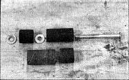
Drum sand the upper insides of the Legs and the underside profiles of the Transition Blocks. Use a 3″ to 4″ long by 1″ diameter Drum Sander for this job. If you don’t have such a Sander, you can make a 3″ Sander by combining a 1″ x 1″ and a 1″ x 2″ Sanding Drum as shown in Fig. 1…or a 4″ Sander by combining two 1″ x 2″ Drum Sanders. Use long carriage bolts and washers to connect the Drums together, then secure the assembly in your Drill Chuck Jaws (See Fig 2.).
Sculpting the Legs
Divide the Leg and Foot into quarters and mark the control lines as shown in Figure 3.
Use masking tape or duct tape to shield the corners of the Transition Blocks from damage during the shaping process as shown in Figure 4.

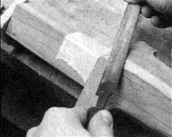
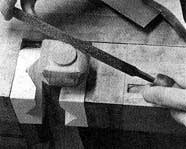
Mount the Leg in a vise. Center and mark a circle on the bottom of the Foot. Use a backsaw to cut the three outside corners of the foot as shown in Figure 5. Cut from the first guideline on one face to the first guideline on an adjacent face.
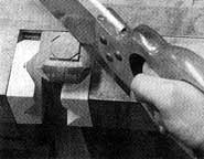

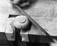
Again, using your backsaw, cut across the corners of the pad to the outside edge of your drawn circle, forming an octagon as shown in Figure 6. Next, undercut these corners to your previous cuts to remove the waste. (See Fig. 7)
Using the edge of a rectangular, double-cut file, round the foot pads to your drawn circles as shown in Figure 8.
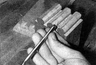
Next, carefully round the three cut corners of the Foot to a circular shape, using a #50 cabinet rasp…then round the bottom of the Foot in a similar fashion. (See Fig. 9)
Mount the Leg in a Bar Clamp then grasp the Clamp body carefully in a bench vise for use as a sculpting fixture. Covering the Bar Clamp jaws with Double-stick tape will provide an improved non-slip grip.
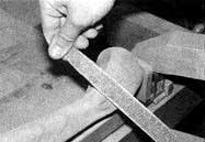
Again, using your cabinet rasp, chamfer your Leg stock carefully at each corner, moving from the first line on one face to the first line on the adjacent face, as shown in Figure 10. Feather the flats progressively narrower to a point at the top, both sides and rear of the Knee…and both sides of the Foot. Feather a flat on the top of the Foot, making it wider, so the top is slightly flattened (See Fig 11).
Loosen your bar clamp, rotate the Leg a quarter-turn and re-secure the clamp. Chamfer all four corners of each Leg in a similar fashion.
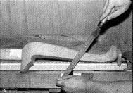
Sculpt the Legs and Feet until they are close to their desired (and hopefully, identical) contours by filing each corner around the Legs to their marked centerlines. Additional rounding will be necessary. Be sure to leave some material for later removal by sanding. Take your time! (See Fig. 12.)
Sanding the Legs
Mount a pneumatic, contour sander in your Lathe and use it to bring the Legs to their final profile. Start with a coarse sleeve, then move to progressively finer sleeves, removing all filing and sanding marks as you bring the Legs and Feet to their final shapes. Remember to always sand with the grain whenever possible. (See Fig. 13.)
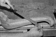
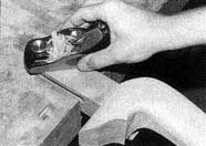
Use a small block plane to smooth the Leg Posts. It must be VERY SHARP, because you’ll be planing nearly across-grain and a dull plane iron will surely tear the wood. (See Fig. 14.)
Making the Table Skirts
Start by marking-out a trial tenon on an identically-sized piece of scrap. Using this scrap piece, set-up your Table Saw and make the cuts with a Tenoning Jig.
As an alternative, you could also use your Rip Fence as a stop to position the shoulder of the Tenon and your Miter Gauge to guide your stock past the blade as you make your cuts.
Next, fit your tenons into their respective mortises, using a sharp bench chisel. Use your Disc Sander to chamfer the tenon ends slightly to allow for glue and make them easier to insert into their mating mortises.
Once you’re confident that the joinery fits properly, trace a line on the tops of the Transition Blocks along the side. Round the top of the Transition Blocks to meet the line marking the bottoms of the Skirt edges.
Stack together and align the bottom edges of all similar Skirts and Lower Rails. Use masking tape to hold them together in the stacks. Layout each pattern on the top board of each stack, then use your Bandsaw to pad saw the lower contours of all Skirt and Rail sets.

Carefully cut the Drop Leaf Supports out of the Coffee Table side Skirts while they’re still taped together. Use the long Drum Sander you created earlier to sand all the sawn contours BEFORE un-taping the stacks.
Once the sawn edges are sanded, tape the Drop Leaf Supports back into position in the Skir>ts from which they were removed. Using your Horizontal Boring setup, drill and counterbore the support pivot holes for #10 x 1-1/2″ round-head wood screws. Install the screws and un-tape the supports.
Using a ripping blade on your Table Saw, cut the Top Retainer Slots in the Side skirts of the Coffee Table — and the Upper Front Rails and the End Skirts of the End Table and the Corner Table. Mounting the Top Retainers in these pieces will allow unrestricted expansion and contraction of the tops with changes in temperature and humidity. Also, the Inside Drawer Glide will not interfere with the Top Retainer installation.
Prior to assembly, sand the Skirts and Rails thoroughly to remove any planer or Belt Sanding marks.
Drawer Glide Construction
The End Table and Corner Table Drawer Glides are formed by simply cutting rabbets in the edges of narrow boards. However, prior to making these rabbet cuts, drill and counterbore the holes for #10 x 1-1/4″ roundhead wood screws in the edges of the stock, then cut the notches in their ends using your Bandsaw. Finally, form the required rabbets by using your Table Saw with a Dado Blade or Molding Set-up and a straight-edged 1″ Jointer Knife Set.
Insert the screws into the drilled holes and use them as “punches” to mark the pilot hole positions on the inside of the Sides. Use your Drill Press with a 1/8″ bit to drill the pilot holes in their marked positions.
Table Assembly
Prior to gluing-up the Tables, dry assemble and clamp each Table together to verify the proper fit of all components. If all goes together nicely, remove the clamps and disassemble the pieces.
Start the assembly process by gluing and clamping the front and rear pieces to their Legs. Be sure to wipe the glue squeeze-out from the wood with a water-soaked rag. Once the glue has dried thoroughly, assemble the Front and Rear sections together with the Sides and remove the glue squeeze-out in the same manner.
Drawer Construction
Begin by measuring the drawer openings to double-check the drawer sizes against the List of Materials…then cut all Drawer components to size, as required. Plan to leave a 1/16″ space on the Drawer Sides and Tops to provide room for the Drawers to move in and out freely. Remember, the Drawer Fronts are larger than the openings to allow for 3/8″ rabbets on the insides to recess the Fronts.
Cut the rabbets around the Drawer Fronts. Use your Jointer, Router Table Set-Up or Shaper to achieve the smoothest possible cuts.
Drilling Drawer Front Sockets
Lay out the joinery on a piece of identically-sized scrap stock. Remember, this piece must be EXACTLY the same thickness and width as the Drawer Fronts (length isn’t critical).
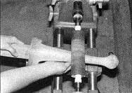
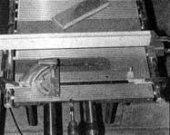
Using the Horizontal Boring set-up, use your Miter Gauge as a guide and sliding position controller. Working with a 5/8″ Brad Point Drill Bit, clamp stop blocks in the Miter Gauge slots to limit the travel of the Miter Gauge when drilling the upper and lower side sockets (See Fig. 15). Use an easily-removable 1″ long wooden spacer to fit between your Stop and the Miter Gauge Bar to position the center hole. All three hole positions MUST be EXACTLY symmetrical from the center of the width of the front and no more than 1/64″ away from the edge of the rabbet.

Use your trial piece of stock with the joinery laid out on it to set up the stops on the exact centers and drill the 1/2″ deep test sockets.
Once all is set precisely, position the Rip Fence as a back stop and set your drilling depth-of-cut to the exact thickness of the sides. Drill all sockets in the ends of the first Drawer Front (See Fig. 16). Reposition the Fence and Depth Stop accordingly and drill the Sockets in the second Front. DO NOT CHANGE THIS SET-UP…it will be used later!
Cutting Drawer Side Pins
Lay an end of a Front piece on a stack of corresponding Side pieces that have been taped together in perfect alignment and hold the Front piece firmly against the end of the taped-together sides. Align the bottom of the sides with the bottom rabbeted edge of the Front and trace the positions of the sockets onto the top side of the stack of Sides (See Fig 17.)
Pad saw all of the Drawer Sides to the traced sockets using your Bandsaw with a 1/8″ Blade. Be sure to stay on the OUTSIDES of your lines.
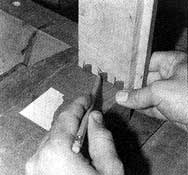
Using an EXTREMELY SHARP bench chisel, carefully shave the pins cross-grain, just to the cutting line while all the pieces are still taped together (See Fig. 18). Verify the fit of the pins to the sockets in the Front piece by checking them at both sides of your stack.
When you’re confident that the fit is perfect, untape your stack of Side Pieces. Trial assemble the Sides in their proper positions and make any adjustments to their fit, if necessary.
Drilling the dowel holes in the Tails
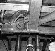
Using the same Horizontal Boring set-up that you used to drill the sockets in the Drawer Fronts, dry assemble the Drawer Fronts and Sides then drill 1/4″ diameter dowel holes through the exact centers of the Tails and into the Drawer Fronts (See Fig. 19). Number each assembled Drawer joint so you’ll know which pieces join together during the final assembly process.
Using a 1/2″ wide Dado set-up on the Table Saw, cut the vertical back Dado in each Drawer Side. Then use a 1/4″ wide Dado set-up to saw the bottom grooves in each Drawer Side. Do not glue-up the Drawers yet.
Making the tops
Saw, joint and glue-up the stock for the three Top pieces. Use a Hand Scraper to scrape away the excess glue and plane and/or sand the pieces smooth. Cut the Top pieces to size according to the List of Materials.
Use the Shaper set-up with a Drop-Leaf Cove Cutter and Drop Leaf Bead Cutter to cut the rule joints on the edges where the Center Top piece and Drop Leaf side pieces of the Coffee Table meet.
While you have your Shaper set up, change to a 1/4″ Quarter-Round Cutter and round-over the top edges of the Drawer Sides. Switch to the Bead & Quarter-Round Cutter and cut the decorative thumbnail edges around the Drawer Fronts.
Next, clamp the three Coffee Table top parts gently together while you lay out the Top profile. Since each drop-leaf joint will overlap by about 3/8″, the finished size of the Top will be 30″ x 40″.
Turn your Table over and draw your oval layout on the underside. Begin by drawing perpendicular horizontal and vertical centerlines for your oval as shown in Fig. 19-A. These lines will be your minor (A/B) and major (C/D) axes.
Set a large compass to the distance CX (in our case, this should be half the width of our Table Top or 20″). Position the compass point at location A and strike an arc across the major axis line at points #1 and #2.
Take a long piece of string or heavy thread and tie it intoa continuous loop that will be equal to the distance between points “C” and “2”, when the loop is pulled taut (In other words, if your push pins were inside your tied loop at points “C” and “2”, the loop would be taut.)
Drive your two push pins lightly into the underside of the Top at points #1 and #2 on your layout. Slip your tied loop over the outside of you push pins. Position the point of a pencil or marker inside your string loop at location “A” and begin moving you pencil or marker point around the layout in a clockwise manner…dragging the string loop with you as you finish drawing your oval.

Mortise and mount the drop-leaf hinges to the underside of the Top. Note the relationship of the hinge pin in the joint (See Fig. 20). Remove the clamps.
Use your Bandsaw to cut the oval profile, then carefully sand the edges smooth using your Disc Sander. Next, use a Guide Pin Shaper set-up with an >Ogee Cutter and Rub Collar to cut the decorative edge around the assembled oval Coffee Table Top. This set-up will allow the Shaper to cut into the Top slightly beyond what the plans call for. Sand away this unwanted ridge around the edge with your Disc Sander.
Drill the Top retainer screw holes on the underside of the table Tops, 1-1/2″ away from the Leg Post positions.
Assemble the Drawers with glue, 1″ long Drawer dowels and bar clamps. Wipe the glue squeeze-out from the wood with a water-soaked rag.
Sand, sand, sand and sand some more…then apply the finish of your choice.
* Increase the length of these pieces as shown in parentheses to make the End Table into the Corner Table and double the number of pieces required.
** Add 1/4″ to the length if making a higher foot pad for use on plush carpeting